Modifications
AGC Kit Updates
Important Update:
Changes to AGC PCB Design for Improved Performance
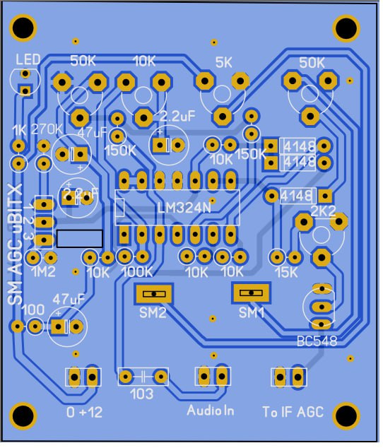
AGC PCB CORRECTION
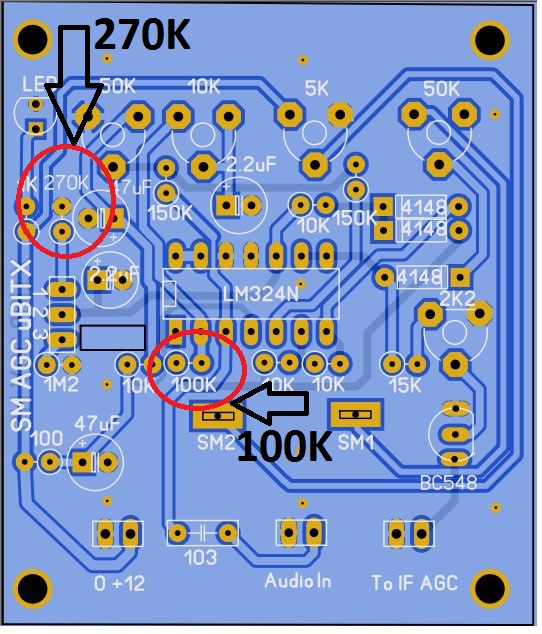
CORRECT PCB SILK SCREEN
We would like to inform you about recent modifications made to our Automatic Gain Control (AGC) PCB, aimed at enhancing its functionality and addressing certain issues reported by our customers. These changes have been implemented to ensure a better user experience and improved performance of our AGC system.
Previously, our AGC PCB featured multi-turn presets, which allowed for precise tuning. However, we received feedback from some users regarding difficulties encountered while adjusting the multi-turn presets. In response to this valuable feedback, we have made significant alterations to the PCB design by replacing the multi-turn presets with non-multiturn presets. This change aims to simplify the tuning process and provide greater ease of use.
During the PCB design process, we encountered an unfortunate oversight that led to the omission of certain components from the silk screen. Specifically, there were two resistor-related issues. First, a 270K resistor was missing, which should have been clearly indicated on the PCB. We have marked the location of this resistor with a circle in the accompanying picture on our blogpost. Additionally, there was an error in the marking of another resistor. Instead of being labeled as 100K, it was mistakenly marked as 10K on the PCB. We have also highlighted this discrepancy with a circle on the PCB.
We want to assure you that while these component issues occurred, the remaining components on the AGC PCB are functioning correctly and as intended. The AGC system utilizes the LM324 IC and a VU Meter for accurate signal strength measurement. It is compatible with any transceiver, allowing for seamless integration into your existing setup.
We deeply apologize for any inconvenience caused by these oversights and mistakes. We are committed to rectifying the situation promptly and providing you with the best possible product. To address these issues, we have taken the following measures:
- Updated PCB Design: The AGC PCB has undergone modifications to replace the multi-turn presets with non-multiturn presets, ensuring easier and more user-friendly tuning.
- Component Additions: The missing 270K resistor, as well as the mislabeled 10K resistor, will be included in all future AGC PCB shipments. We have rectified these issues to maintain the proper functionality of the AGC system.
- Updated Documentation: Our blogpost and associated resources have been updated to reflect the changes made to the AGC PCB design. The picture with clearly marked circles will be provided to help you identify the correct locations for these resistors.
We value your trust and strive to deliver top-quality products and services. If you have any further questions or concerns regarding these changes or any other aspects of our AGC system, please do not hesitate to reach out to our customer support team. We are here to assist you in any way we can.
Thank you for your continued support and understanding. We remain committed to providing you with the best possible solutions for your transceiver needs.
Sincerely,
Sunil VU3SUA