Podcast
Podcast Understanding Easy Bitx Dual Band Transciever For 20 MT/40MT
16
Dec
Dec
Podcast Understanding Easy Bitx Dual Band Transciever For 20 Meters And 40 Meter Bands
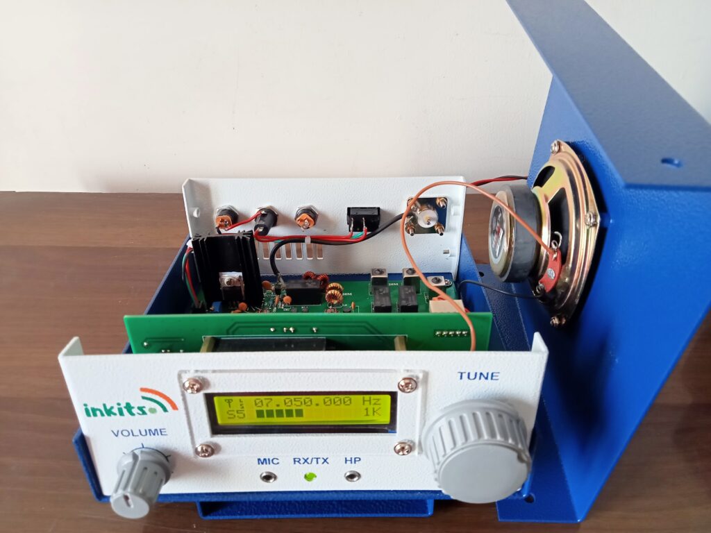
Easy Bitx Dual Band 20MT/40MT Radio: A Construction and Operation Guide
This document summarizes the key points from the “Easy Bitx Dual Band 20MT/40MT Manual” by Paul Ross, offering a concise guide for building and operating the radio.
I. Preparation and Initial Steps:
Initial Check: Before beginning assembly, inspect all parts for damage and ensure all components listed in the Bill of Materials (BOM) are present.
Tools and Resources: Gather necessary tools including a soldering iron, solder, screwdrivers, pliers, wire strippers, multimeter, magnifying glass, and heat sink compound. Print the BOM, schematic, and top-of-board silkscreen for reference.
Component Organization: Organize resistors and small capacitors by value on a sheet of paper for easy identification. Use a multimeter to verify resistor values.
Read Thoroughly: Familiarize yourself with the entire manual, paying close attention to the recommended part insertion and soldering order to prevent errors.
II. Back Panel and Top Panel Assembly:
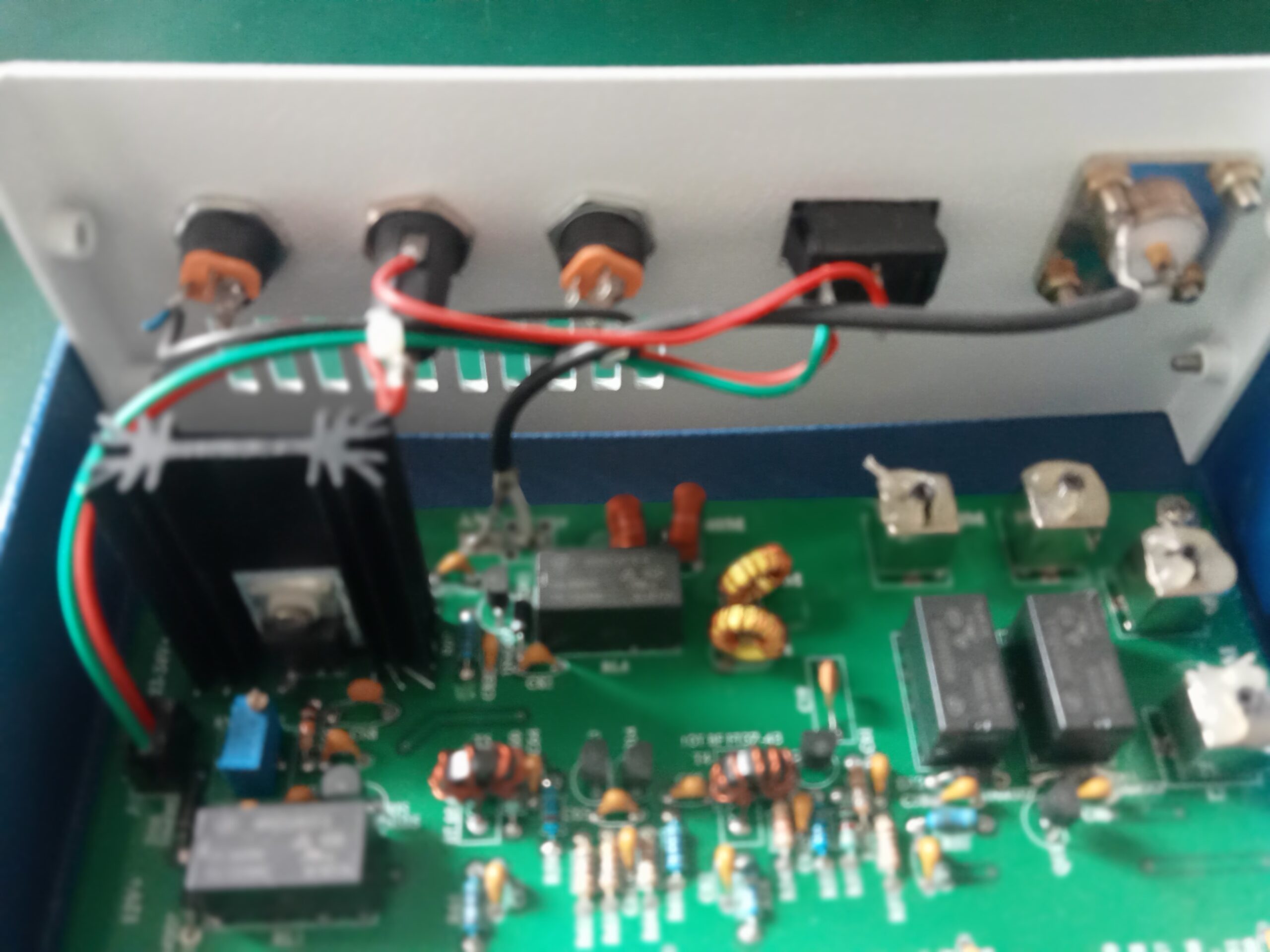
Back Panel Wiring: Begin assembly by wiring the back panel, ensuring the correct fuse type (5MT, 2 Amps max) and verifying the functionality of the ON/OFF switch and coaxial power jacks using a multimeter. Secure the power cable using zip ties.
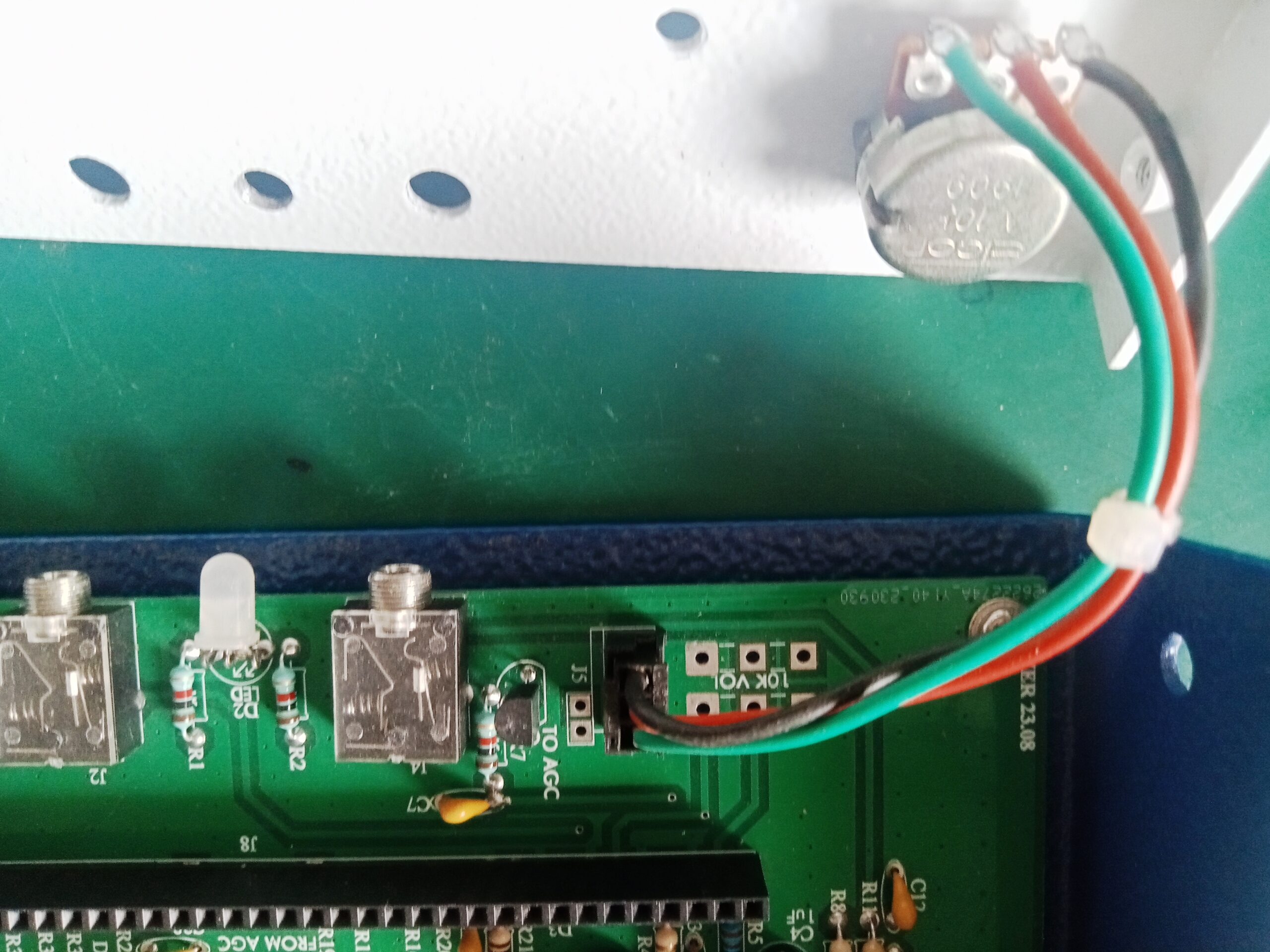
Top Panel Assembly: Wire and mount the loudspeaker, securing the wire with a zip tie. Attach the support bail, insulating the bosses to prevent contact with the PC board. Wire and mount the volume control and encoder, removing the encoder knob’s face for shaft access.
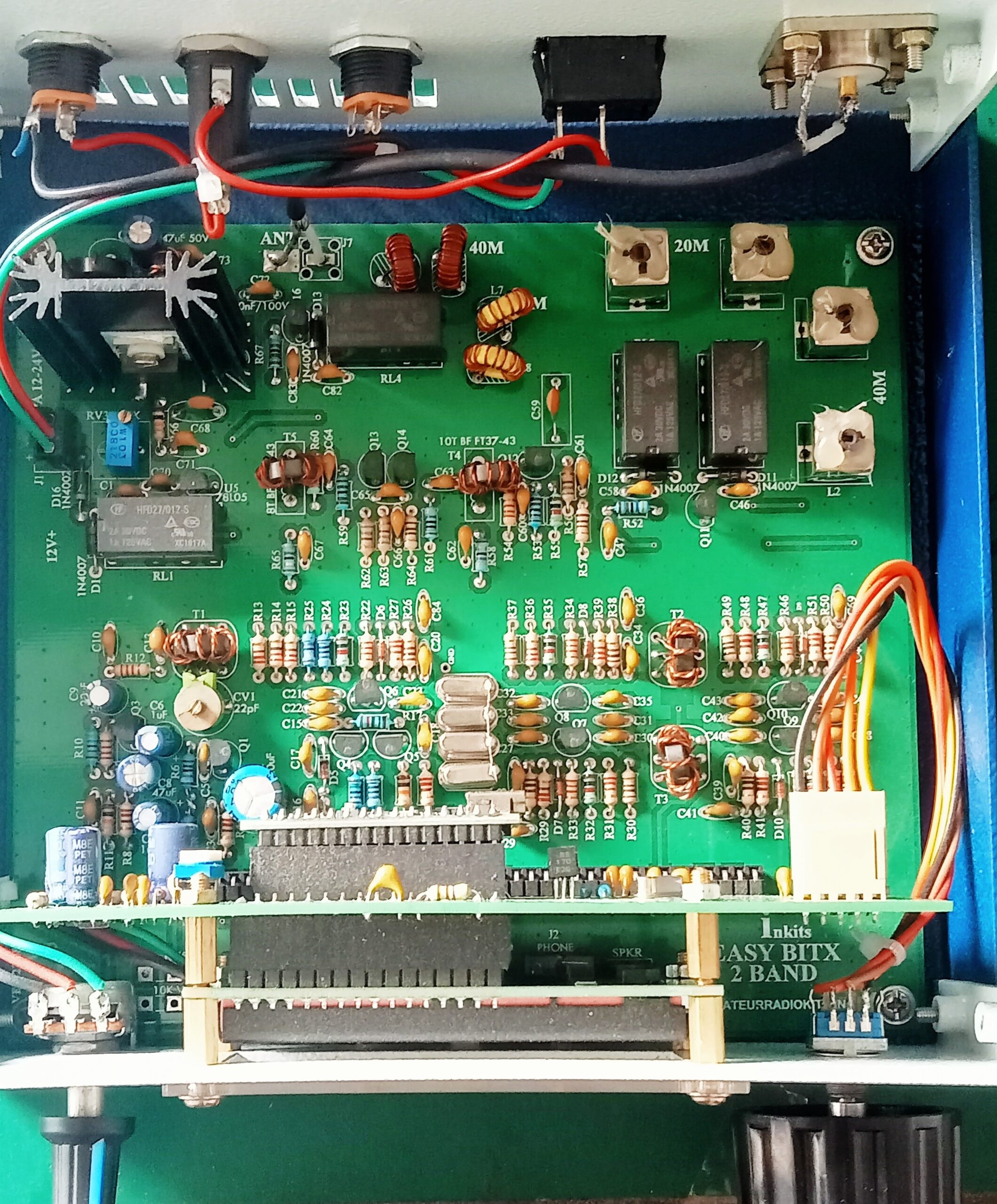
III. PC Board Component Insertion:
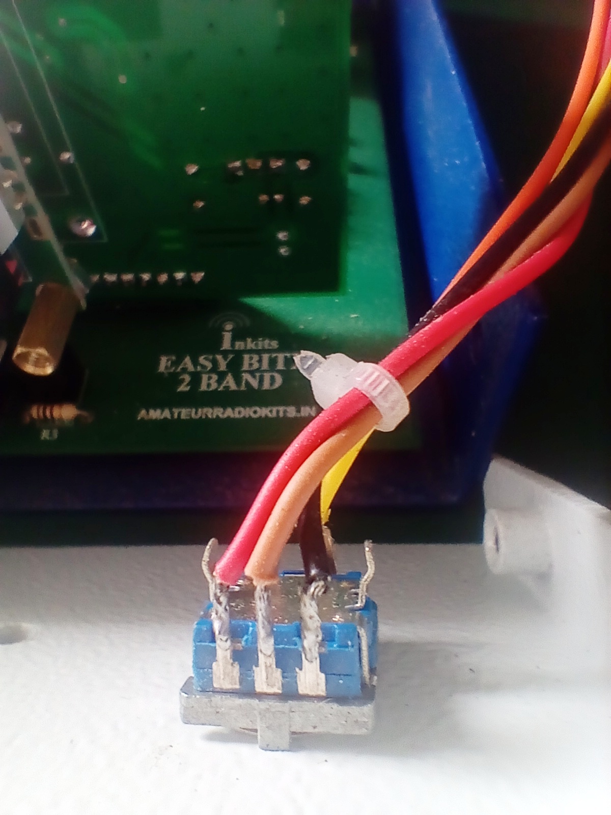
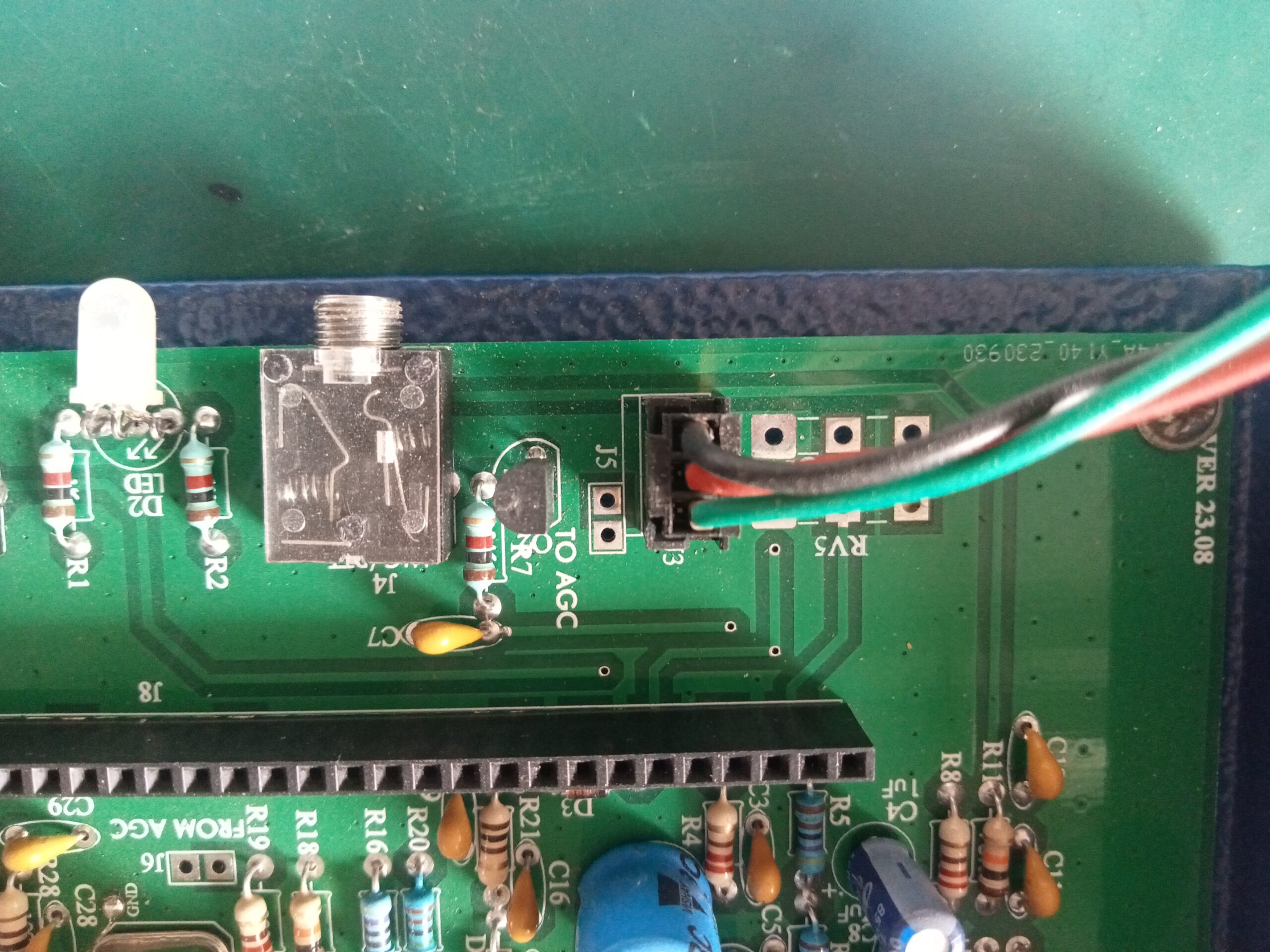
Initial Components: Solder the jacks for power, volume, speaker, microphone, and headphones (J1-J4) as well as optional AGC board jacks (J5-J6).
Display & Processor Socket: Carefully solder the multi-pin socket for the display and processor, ensuring all pins are properly connected and the socket sits flush against the PC board.
Test Fitting: Temporarily attach the PC board to the front panel to confirm proper alignment and clearance of the microphone and headphone jacks.
IV. Component Installation (continued):
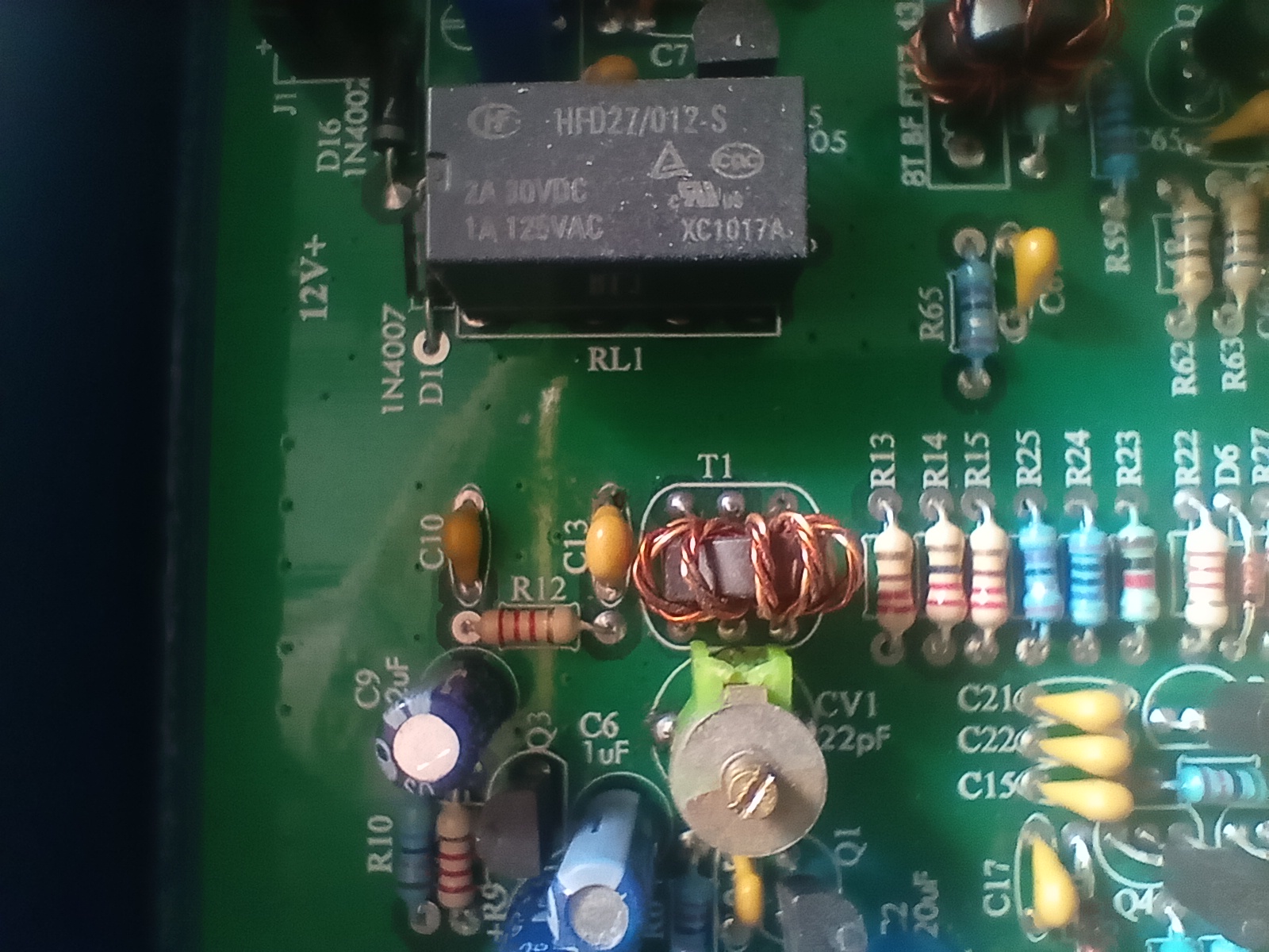
Relays, LED, Regulator: Mount the four T/R relays flush with the PC board. Install the three-lead T/R LED, ensuring proper alignment with the front panel hole. Solder the 78L05 regulator chip (U5).
Capacitors: Install the six electrolytic capacitors, observing polarity markings. Install the four 10MHz crystal filter crystals, securing them with a wire to ground.
Diodes: Install the five 1N4007 diodes, aligning the band on the diode with the marking on the silkscreen. Note: 1N4148 diodes are not used in this version.
Transistors: Install the fifteen 3904 transistors, aligning the flat side of the case with the “Q” markings on the PC board. The final amplifier transistor (Q15) and heat sink are installed later.
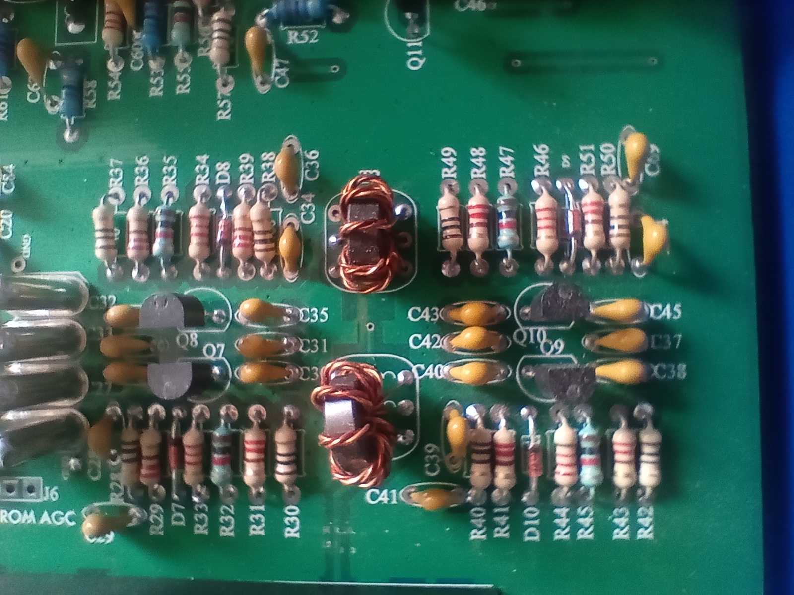
Remaining Components: Install the five Mylar capacitors, the trimmer capacitor (CV1), the fifty-three 100nF ceramic bypass capacitors, and all resistors. Use the BOM and a multimeter for verification.
Bias Potentiometer: Mount the multi-turn 10K potentiometer (RV3), connecting a jumper wire between the junction of R66-C71 on the back of the board.
V. Final Amplifier, Filters, & Transformers:
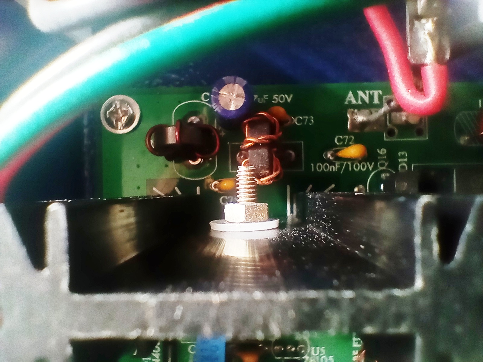
Final Amplifier: Assemble the heat sink to Q15 (IRF510) with provided hardware, using heat sink grease and ensuring insulation between the transistor tab and heat sink. Solder the transistor leads after mounting.
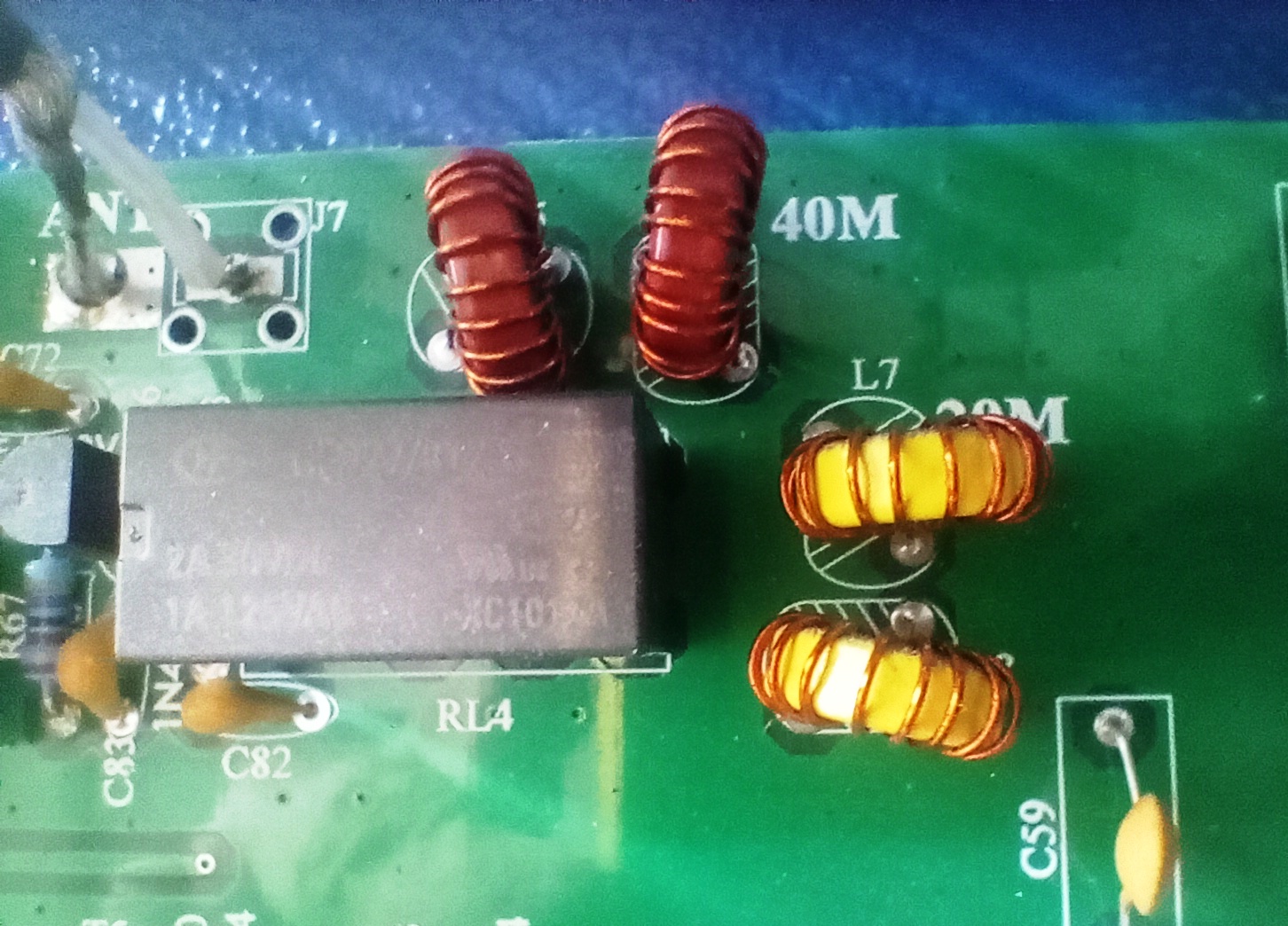
TOKO Band Pass Filters: Wind the four TOKO filters for L1-L4, following the specified number of turns and pin connections for each band (40m and 20m).
RFC-1 & Low-Pass Filters: Wind RFC-1 (FT37-43 toroid) with 15 turns. Wind L5-L8 (low-pass filters) using the specified toroid types and turn counts.
Transformers: Wind transformers T1-T6, following the instructions and using the designated toroid types and winding techniques (trifilar or bifilar).
VI. Final Assembly & Testing:
Inspection: Inspect all solder joints for quality and correct any issues. Insulate areas where the PC board is close to the front panel bosses.
Board & Panel Mounting: Attach the PC board to the chassis bottom, followed by the back panel and front panel. Secure all mounting screws and attach knobs.
Display & Coaxial Cable: Insert the display unit into the PC board and attach it to the front panel with screws and the Plexiglas cover. Solder the coaxial cable to the UHF connector and secure it.
Bias Setting: Connect a dummy load and multimeter in series with the power supply. Apply +12V and activate PTT, adjusting RV3 to achieve a 50mA current reading. Adjust the balance capacitor for minimal RF output with no modulation.
VII. Operation: The Easy Bitx Dual Band Transceiver offers a user-friendly experience, making it ideal for individuals seeking a seamless communication solution. With a clear understanding of the Easy Bitx’s functionalities, users can effortlessly operate the device and enjoy its reliable performance.
Basic Connections: Connect the microphone, power supply, and antenna. Headphones can be used and will disable the loudspeaker.
Controls: Use the encoder knob to tune frequency. A single push changes the frequency step, a double push changes bands (40m/20m), and a press-and-hold adjusts the BFO.
Volume Control: The volume control knob increases volume when rotated clockwise.
Screen Adjustment: The screen appearance can be adjusted using the potentiometer on the back of the display panel.
This document provides a summary of the key points in the manual. Refer to the original manual for detailed instructions, diagrams, and safety information.
Download Manual .
https://drive.google.com/file/d/1JsIeZo1JEIX2kQISKLH4vDJGHHtl-J-W/view