Educational
Faceplate Designs For Ham Radio Transceivers

Dec
We have published a few designs of Faceplate if you plan to build a case yourself for micro bitx or any other transceiver of your choice.
A software like the Front Designer can be used for the same. Since its our work to build different type of case designs for radio equipment we made a few Faceplate designs, you could freely use them for your use. Front Designer can be downloaded for free but is a demo version which is free to use, it will design but not save, to save on your pc you are required to purchase the software.
Dimensions are not given but the picture would give you an idea as to what your design should be like.
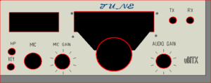
- Faceplate with following sockets and displays. Headphone, Key, Mic Socket, Mic Gain, Audio Gain, Main Tune in center with 1602 display on top. TX And RX led indicators on top right side of faceplate.
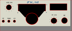
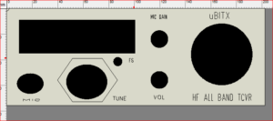
2. Faceplate with following sockets and displays. Headphone, Key, Mic Socket, Mic Gain, Audio Gain, Main Tune in center with 1602 display on top. Mic Gain And Mic Socket on right with a VU Meter on the extreme right side of the faceplate
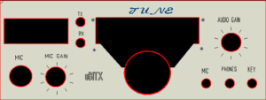
3. Faceplate with following sockets and displays. Headphone, Key, Mic Socket on right side and, Mic Gain, Audio Gain on Left side. Main Tune in center with 1602 display on top. Mic Gain And Mic Socket on left side with a VU Meter . TX and RX led indicators next to the VU Meter.
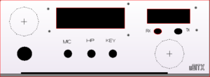 4. Faceplate with following sockets and displays. On top extreme Left we have the volume control with Big knobs size 36mm, just on bottom a Mic socket XLR type with 4 or 8 pins . In center we have a 1602 LCD display and below the LCD we have the sockets for Mic,Head Phones And Key. The extreme right side has a VU meter and below it we have Led Indicators for RX And TX, just below Led indicators we have the Main Tune Control. Where an encoder and Knob of 36mm are used.
This type of design is suited for Right Handers. Now if we just interchange the Main Tune And Audio Gain 10K Pot
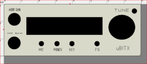
5. This faceplate is quite different from the ones published above. The extreme left top has a 1602 LCD display and below we have a Mic Input XLR socket 4 Pin or 8 Pins as per ones own choice can be used. The center of the faceplate has Main Tune Dial for tuning the frequency, and just on top right is a micro switch for Menu . a suitable led also could be used here for indication of power on or tx on. In the center we have the Mic Gain Control and the Volume Gain control. The extreme right side has a 36MM knob with encoder for tuning the frequencies.
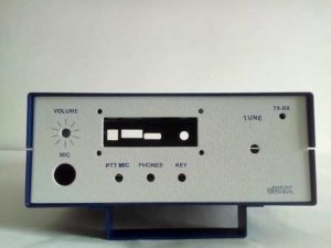
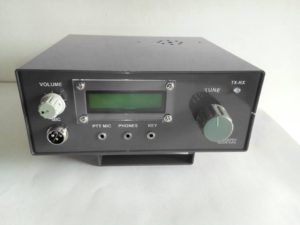
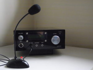
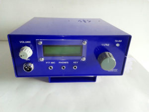
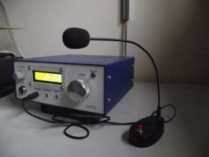
6. Now this faceplate design is quite well known as this has been used in our ubitx case design and we have sold in large quantities these cases with various colors.
The Audo Gain control is on the extreme left side on the top. Below we have the Mic Input XLR connector.
The center has a 1602 LCD and below we have the 3.5 mm stereo sockets for Mic,Phones And CW key. And Menu switch which we did not use in our case. The right side has a 36MM knob with use of a encoder for frequency tune, next to the Dial is a Led For TX and RX indication.
Pictures of micro bitx case below using this design.
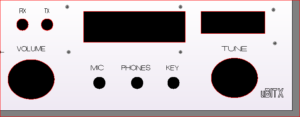 7. This faceplate has two led TX and RX on the top left side of the volume control audio is placed just below the led.
LCD Display 1602 is placed in the center with 3.5 mm stereo sockets in the center for Mic, Phones And Key
functions, A VU Meter 250ua is placed on the top of right side of faceplate. Main Tune control of a encoder and 36mm Knob is placed below the VU Meter.
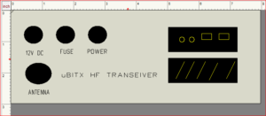 8. This picture is of the rear panel for the ubitx case. On extreme left we have socket for DC input 12 Volts.
followed by a 2 Amp fuse, and On/OFF switch. The right side has a USB connector , D9 Connector and two nos of
2.5mm stereo sockets. The stereo sockets are for any that may be found suitable. The USB connector can be used to connect the Raduino with the USB port, so you could re-programme the software without taking out the Raduino.
The D9 connector could be used for any suitable use, old pc had a serial port which could be connected with the d9 connector and used for CW mode from pc using a software. The d9 connector would act here as a PTT switch getting command from PC for using cw keying.
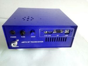
Picture of ubitx case with rear side.
[xyz-ihs snippet=”adsense-auto-2″]